Voltage divider
In electronics, a Voltage Divider, also called Resistor Divider, is a design technique used to create a Voltage Vout which is proportional to another Voltage Vin. A Voltage Divider whose Resistance is variable is called a Potentiometer, Figure 1.
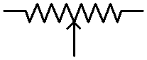
Figure 1: The Schematic symbol for a Potentiometer
Figure 2 is a simple circuit to explain the principle of Potentiometer. A Resistor R is divided into two Resistors, R1 and R2, by the Voltage Divider Sliding Contact, which can move to any position along the R. R1 and R2 are connected in Parallel to the two Light Bulbs, B1 and B2, respectively. The two Parallel circuits are then connected in Series with the Voltage Power Supply V.
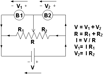
Figure 2: The Equivalent Circuit Diagram
The position of the sliding contact determines the resistances of R1 and R2. As R1 and R2 are changed, the voltages, V1 and V2, across each Light Bulb change. Because the sum of R1 and R2 is a constant (R), one Light Bulb becomes brighter while the other becomes dimmer. The sum of the voltages, V1 and V2, across each Light Bulb is equal to the Power Supply Voltage V.
The volume control on the radio or TV is one of the applications of a Potentiometer, Figure 3. The volume control uses the technique of Voltage Divider. The higher the divided Voltage to the Audio Output Amplifier, the louder the sound we hear.
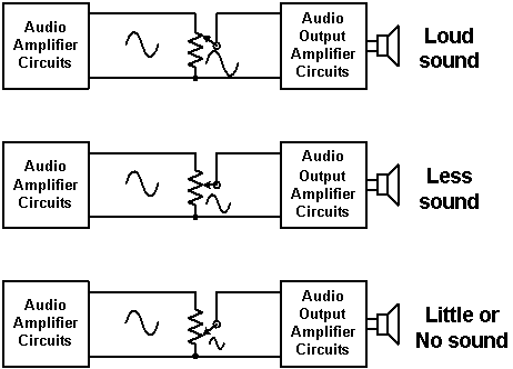
Figure 3: Volume Control on the radio or TV
About CMM
Contact US
Others
Other Websites
Number of Visitors:
Last Modified Date: 10/3/2025