How a diode works
The Diode can be considered as the simplest and most fundamental element in electronics, which is composed of a p-n Junction. It is a two terminal device, Figure 1a. Figure 1b shows its schematic symbol, where the "+" terminal is called Anode and is connected to the p-Region and the "-" terminal is called Cathode and is connected to the n-Region. The Diode operates in three different states: Forward Bias, Reverse Bias and Breakdown, Figure 2.
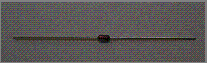 Figure 1a: Diode
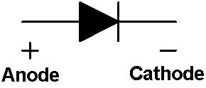 Figure 1b: Schematic Symbol of a Diode
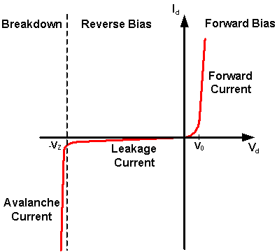 Figure 2: The Current-voltage Relationship of a Diode
In order to Reverse Bias a Diode, the Diode is placed in Series with the DC Supply and the Current Limiting Resistor, with the Cathode connecting to the Current Limiting Resistor and the Anode connecting to the Negative terminal of the DC Supply, Figure 3. In this case, there is a Negative Voltage Difference (Vd) across the Diode, only a negligible Current (at the range of nA, 1 nA = 10-9 A) can pass through the Diode, which is called Leakage Current.
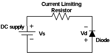 Figure 3: A Diode at Reverse Bias
A Light Emitting Diode (LED) is a type of Diode, Figure 4a. Figure 4b shows its schematic symbol. It is typically made of Gallium Arsenide (GaAs). At Forward Bias, it emits Visible Light. At Reverse Bias, the LED behaves as an Open Circuit and no Light is emitted.
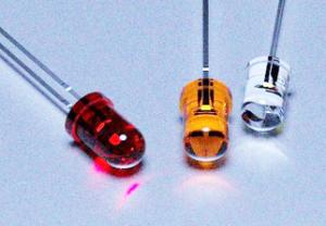 Figure 4a: LED
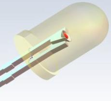 Figure 4b: Schematic Symbol of a LED
About CMM
Contact US
Others
Other Websites
Number of Visitors:
Last Modified Date: 10/3/2025