Inductor in a DC Circuit
An Inductor is a passive device that stores energy in its Magnetic Field and returns energy to the circuit whenever required. An Inductor is formed by a cylindrical Core with many Turns of conducting wire. Figure 1 and Figure 2 are the basic structure and the schematic symbol of the Inductor.
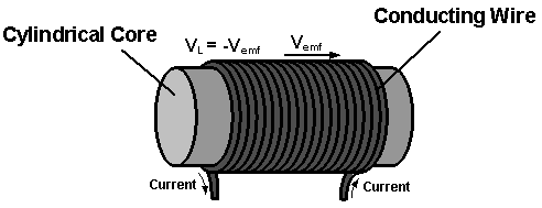
Figure 1: Basic Structure of the Inductor

Figure 2: Schematic symbol of the Inductor
When an Inductor is connected to a circuit with Direct Current (DC) source, two processes, which are called "storing" and "decaying" energy, will happen in specific conditions.
The Inductor is connected to the DC Power Supply, Figure 3. The sudden increase of current in the Inductor produces an Self Induced Electromotive Force, vemf, opposing the Current change, Figure 1. This appears as a Voltage across the Inductor, vL = - vemf. This - vemf will slow down the Current change, and in turn, the slow down of the Current change, will make vL become smaller. When the Current becomes stable, the Inductor creates no more opposition and vL becomes zero, the Storage Phase is over.
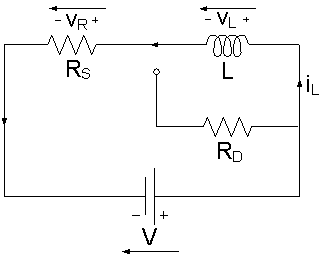
Figure 3: Inductor is Storing Energy
An Inductor is equivalent to a Short Circuit to Direct Current, because once the Storage Phase has finished, the Current, iL, that flows through it is stable, iL = V / R, no Self Induced e.m.f. is produced and vL is zero. The Inductor acts like an ordinary connecting wire, its Resistance is zero. The Current iL through an Inductor cannot change abruptly.
When the Inductor is disconnected from the Power Supply, Figure 4, vL reverses polarity and drops instantaneously from zero to a negative value, but iL maintains the same direction and magnitude. The energy stored in the Inductor decays through the Resistor RD. vL rises gradually to zero and iL drops gradually to zero.
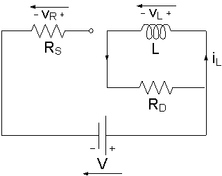
Figure 4: Inductor is Decaying Energy
In Figures 3 and 4, the Resistance of RS and RD affects the storing rate and the decaying rate of the Inductor respectively.
The quotient of Inductance L and Resistance R is called the Time Constant τ, which characterizes the rate of energy storage and energy decay in the Inductor, Figure 5.
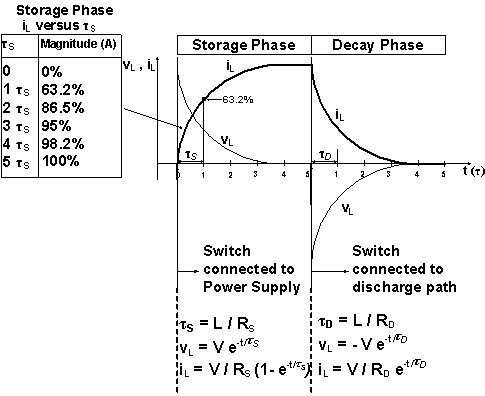
Figure 5: The Voltage VL and Current iL during the Storage Phase and Discharge (Decay) Phase
The larger the Resistance, the smaller the Time Constant, the faster the Inductor stores the energy and decays the energy, and vice versa.
Inductors are found in many electronic circuits. For example, two Inductors can form a Transformer that is used to convert between high and low Voltages, and vice versa.
About CMM
Contact US
Others
Other Websites
Number of Visitors:
Last Modified Date: 10/3/2025