Parallel circuit
A Parallel Circuit is a circuit in which that the Input Terminals and the Output Terminals of the Resistors (or other Electronic Components) are connected together respectively, Figure 1. In a Parallel Circuit, the Voltage V across each component is the same, the Current flowing through each component, Ix, is independent of the others, it depends on the Resistance of that component, Rx, Ix = V / Rx.
The Total Conductance (1 / R) of a Parallel Circuit is the sum of the all Component Conductances, 1 / R = 1 / R1 + 1 / R2 + … + 1 / Rn, Figure 1.
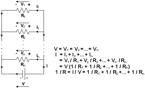
Figure 1: The Diagram of a Parallel Circuit
In Figure 2, two Light Bulbs, B1 and B2, and a Power Supply V are connected in Parallel. The same Voltage V, V = V1 = V2, is applied to the two Light Bulbs. If their Resistances, R1 and R2, are the same, R1 = R2, the Currents that flow through B1 and B2 are also the same, I1 = V / R1 = V / R2 = I2, and they are On with the same brightness.
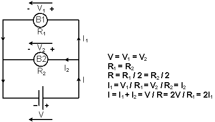
Figure 2: The Equivalent Circuit when two Light Bulbs and the Power Supply are connected in Parallel
If the circuit path of B2 is an Open Circuit, Figure 3, there is no Current flowing through B2, I2 = 0. Thus, B2 is Off. As the Voltage V applied to B1 is unchanged, the Current flowing through B1 will still be I1 = I = V / R1. The brightness of B1 is unchanged.
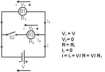
Figure 3: The Equivalent Circuit when B2 is open-circuited
Lights, TV, air conditioner and other Electrical Appliances in your house are connected in parallel.
About CMM
Contact US
Others
Other Websites
Number of Visitors:
Last Modified Date: 10/3/2025