Serial circuit
A Series Circuit is a circuit whose components are connected in a single loop, Figure 1. In a Series Circuit, the Current I flowing through each component is the same, but the Voltage across each component, Vx, can be different, depending on the Resistance of the component, Rx.
The Total Resistance R of a Series Circuit is the sum of the all Component Resistances, R = R1 + R2 + … … + Rn, Figure 1.
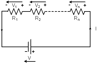 Figure 1: The Diagram of a Series Circuit
In Figure 2, two Light Bulbs, B1 and B2, and the Power Supply V are connected in Series. The same Current I, I = V / (R1 + R2), flows through the two Light Bulbs. If their Resistances, R1 and R2, are the same, R1 = R2, B1 and B2 divide the Power Supply Voltage V equally, V1 = V2 = V / 2, and they are On with the same brightness.
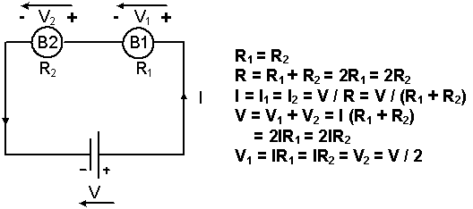 Figure 2: The Equivalent Circuit when two Light Bulbs and the Power Supply are connected in Series
If a Short Circuit is created between the two terminals of B2, Figure 3. All of the Current I, I = V / R1, flows through S2 and no Current flows through B2. B1 becomes brighter and B2 is Off. The Voltage across B1, V1, is equal to the Power Supply Voltage, V1 = V, and the Voltage across B2, V2, is equal to zero, V2 = 0 V.
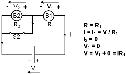 Figure 3: The Equivalent Circuit when B2 is short-circuited
A string of Christmas lights is connected in Series. Once one of the Light Bulbs of the Christmas lights is broken, no Current flows through the circuit and all the lights turn Off.
About CMM
Contact US
Others
Other Websites
Number of Visitors:
Last Modified Date: 10/3/2025