Communications Museum of Macao, 2009 - Electronic Device Construction Competition
Example - "Make an Electromagnetic Crane"
- Principle
- Application of the principle of Lever and the Ampere's law (electromagnetic induction)
- Material
-
The main parts:
- Plastic rods, wooden sticks (can be found in stationery shops)
- Foam board (can be found in stationery shops)
- Powerful permanent magnets: Neodymium magnets (NIB magnet, can be found in electronics stores, Zhuhai)
- Screws, screw nuts and spacers (commonly known as rings, can be found in hardware stores)
- Nails (can be found in hardware stores)
- Enameled wire in 0.3 mm to 0.5 mm diameter (can be found in electronics stores or obtained from abandoned transformer)
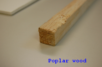
- Poplar wood (commonly used in the aircraft model, can be found in stationery shops)
- Plastic box (can be found in stationery shops or obtained from certain packaging)
- Rubber band (can be found in stationery shops)
-
Control parts:
- D-type battery box: 2 pcs per set x2 or 4 pcs per set x1 (can be found in electrical stores)
- Control boxes (can be found in electrical stores)
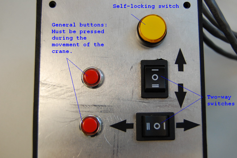
- Button x 2 (general type), self-locking switch x 1, two-way switch x 2 (can be found in electrical stores)
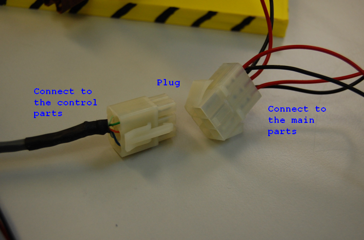
- A set of plugs (can be found in electrical stores)
- The production of the main parts
- 1. The production of the scaffold and the boom:
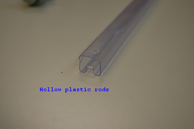
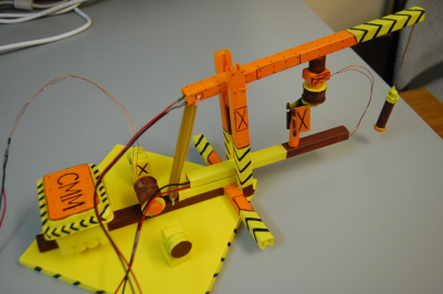
- Hollow plastic rods are used to make the scaffold and the boom (Fig.1) because this material is hard but light. We use adhesive to bind all of the joints because if we use screw locking to bind the plastic joints, it will damage the structure. For details, please refer Fig.2, 3 & 4.
-
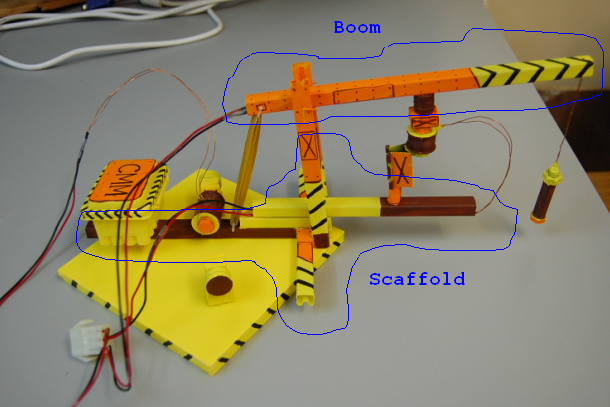
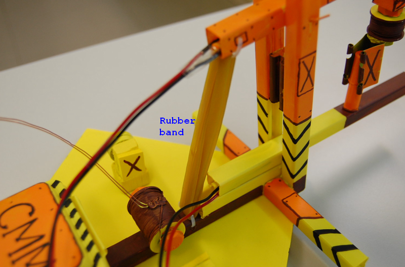
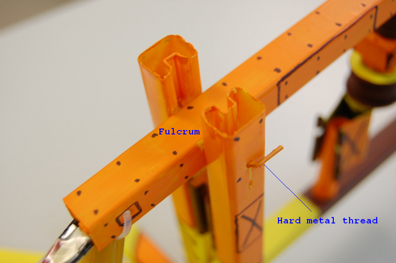
- Using the Principle of Lever to hoist objects, one end of the crane is connected to an electromagnet, and the other is linked to the scaffold with rubber band (Fig.5); the fulcrum of the crane is fixed at the scaffold by using a hard metal thread which makes it rotatable (Fig.6).
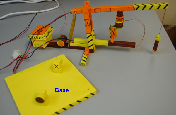
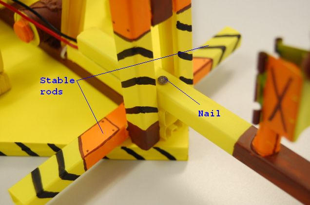
- To enable the scaffold to turn around, a nail is used as a shaft going through the scaffold; and two stable rods are also added to the bottom of the scaffold (Fig.7) to balance the crane while turning around.
-
- 2. Electromagnets and blocks of magnet
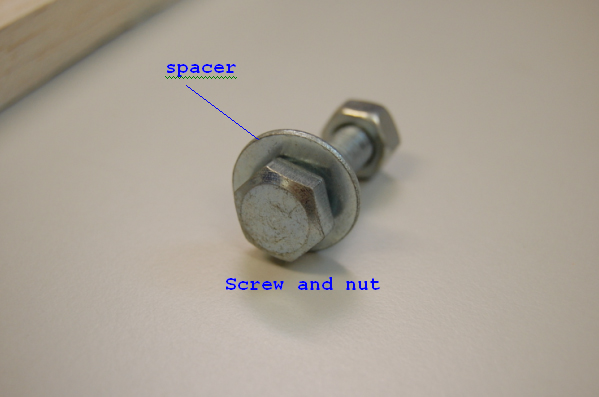
- The iron core of an electromagnet is composed of screws, screw nuts and spacer. Those electromagnets are shown in Fig. 1. According to the Ampere's Law, the more loops the coil has, the greater the attraction and the repulsion force, which enables the electromagnetic crane to move smoothly.
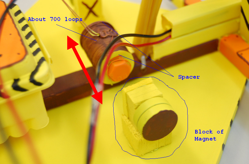
- As shown in Fig.3, the scaffold can turn around via the interaction between the electromagnet A and the blocks of magnet. Therefore, the distance between the two blocks of magnet should not be too large. To have a greater movable range, we recommend using a shorter screw (a 43 mm screw is used in the example) for the core of a coil about 700 loops. As the diameter of the screw nut is not enough to hold so many loops of enameled wire, two spacers should be added at both ends.
-
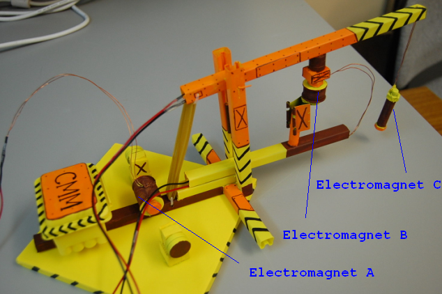
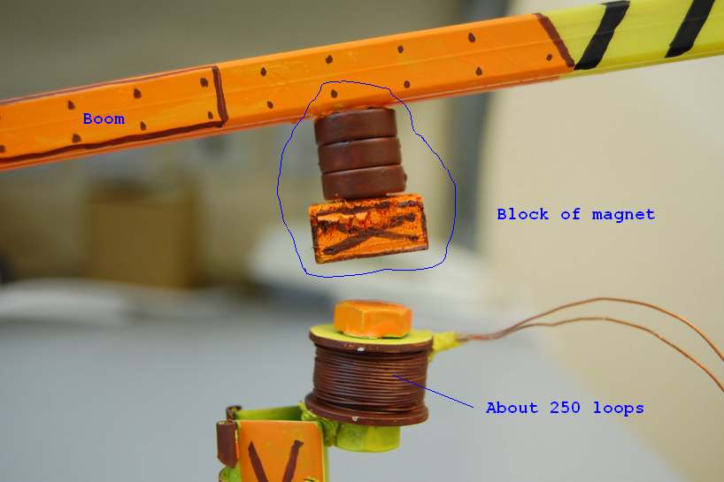
- As shown in Fig.4, the boom can move up and down via the interaction between electromagnet B and its block of magnet. To have a greater repulsion and attraction force, we recommend using a shorter screw (a 25 mm screw used) for the core of a coil about 250 loops, adding spacers as necessary.
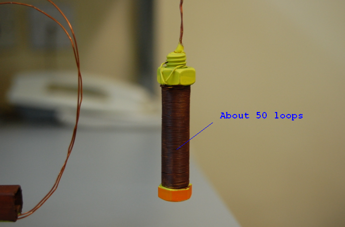
- As shown in Fig.5, electromagnet C does not have any spacers. Due to the limited repulsion generated by electromagnet B, the electromagnet C should be lighter in weight to smooth the up and down movements. We recommend using a shorter screw (about 25 mm) and for the core, a coil about 50 loops will be enough to generate suction.
-
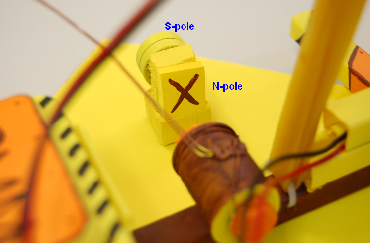
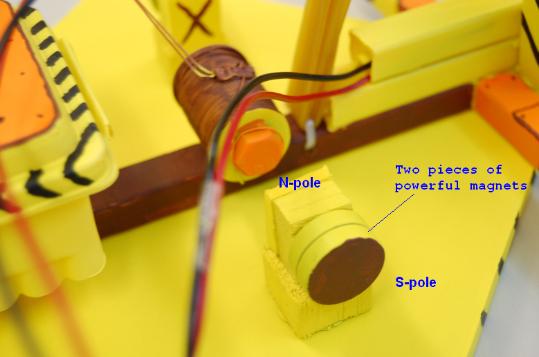
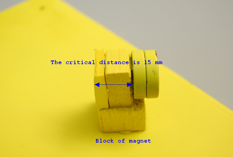
- The objective to make blocks of magnet is to fix the distance between the electromagnets and the powerful magnets. We know that the cores are made in iron. When a core gets closer to a powerful magnet, the suction will be greater and this is not proportional to the distance, so a critical distance exists between the electromagnet and the powerful magnet. This critical distance makes the repulsion generated just stronger than the suction between the core and the powerful magnet. As shown in the sample, we have installed two pieces of powerful magnets at both sides to keep a 15 mm critical distance, and used poplar wood and foam board to separate the blocks (Fig.6 to Fig.10).
-

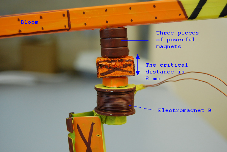
- We use the same method to make a block of magnet for the boom. There are three pieces of powerful magnets in this case to keep an 8 mm critical distance (Fig.11).
-
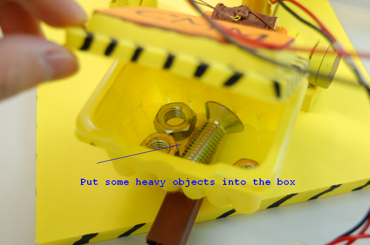
- 3. Production of box with balancing weight and adjustable pole:
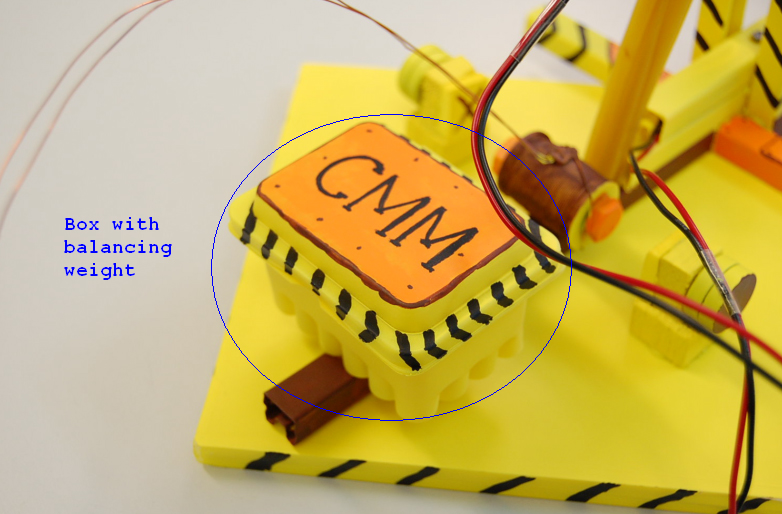
- To obtain a smooth rotation, we added a box with balancing weight to the scaffold to adjust the position of the center of gravity. The material of the box is plastic (Fig.1 & Fig.2).
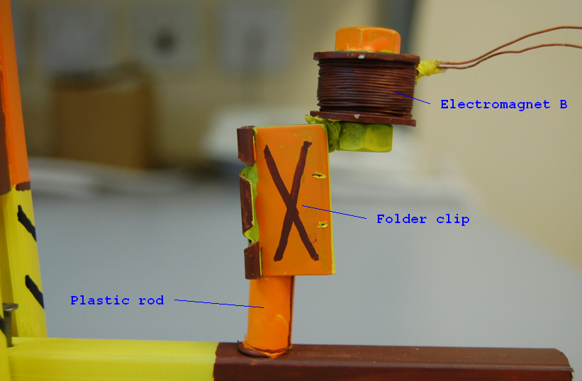
-
- The adjustable pole is composed of two parts: a plastic rod fixed on the scaffold and a folder clip joined to the electromagnet B so that it can adjust the distance between electromagnet B and the block of magnet (Fig.3).
-
- The production of control parts:
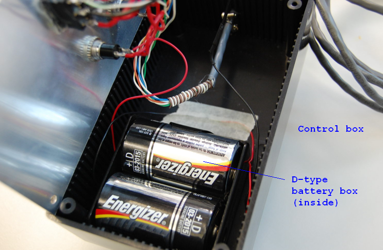
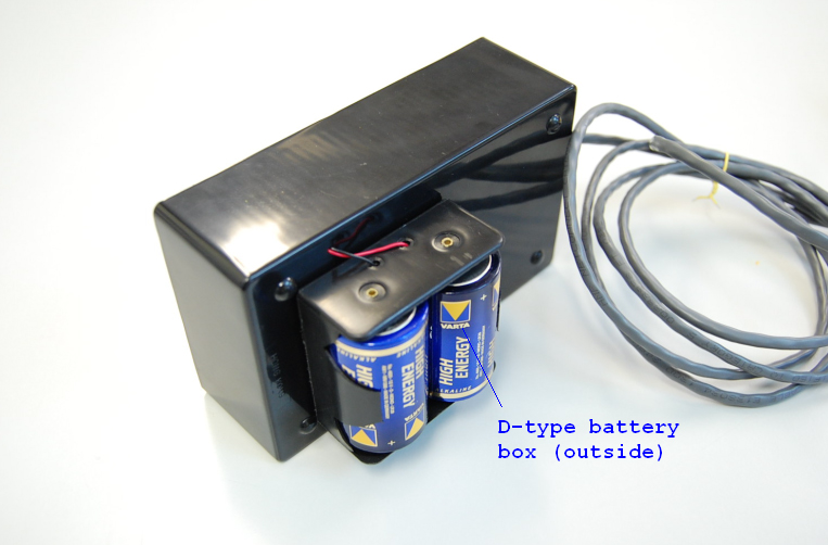
- 1. Production of the power supply:
- Two battery boxes, containing a set of 2 D-Type batteries in each, are installed inside and outside of the control box respectively (Fig.1 to Fig.2). These 4 D-type batteries are now connected in series.
-
- 2. The production of control keys:
- We use here three kinds of switch to control all the actions of the electromagnetic crane: self-locking switch, two-way switch and general button. The self-locking switch can maintain the status in close circuit when you press it and only breaks the circuit when you press it again. So, it is suitable to control the electromagnet C. The general button cannot maintain the status in close circuit unless you press it and therefore, it is used together with the two-way switch to control the actions of the electromagnet A and B shown in Fig.3. These three sets of control keys are connected in parallel. In addition, we use a set of plugs to connect the main parts to the control parts of the crane (Fig.4).
-