Op-Amp-Lab
Op-amps are widely used in analog electronics. The term Operational Amplifier comes from the original applications of the device in the early 1960s. Op-amps, in conjunction with resistors and capacitors, were used in Analog Computers to perform mathematical operations to solve Differential and Integral Equations. The application of Op-amp has expanded significantly since those early days.
One of the most common applications for an Op-amp is to obtain the algebraic difference or sum of two signals or voltages, such circuits are known as Difference Op-amp and Summing Op-amp.
The Difference Op-amp produces an Output Voltage which is proportional to the algebraic difference between its Input Voltages, Figure 1. The Voltage Gain Gv of the Difference Op-amp can be altered by choosing different resistance values. Figure 2 shows an example of the Output Waveform with two Sine Waves as Inputs of the Difference Op-amp.
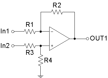 Figure 1: The circuit of a Difference Op-Amp
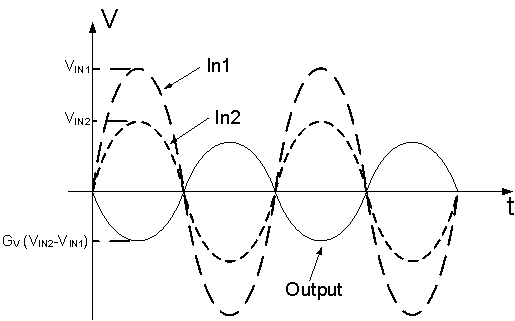 Figure 2: Input and Output Waveforms of the Difference Op-Amp
The relationship between the Input Voltages, VIN1 and VIN2, and the Output Voltage VOUT1 of the Difference Op-amp is expressed as follows:
The Summing Op-amp is a variation of the Inverting Op-amp configuration, Figure 3. The Summing Op-amp has two Inputs, and its Output Voltage is proportional to the negative algebraic sum of its Input Voltages. Figure 4 shows an example of the Output Waveform with two Sine Waves as Inputs of the Summing Op-amp.
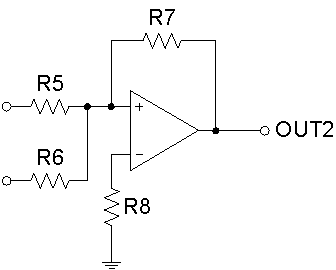 Figure 3: The circuit of a Summing Op-Amp
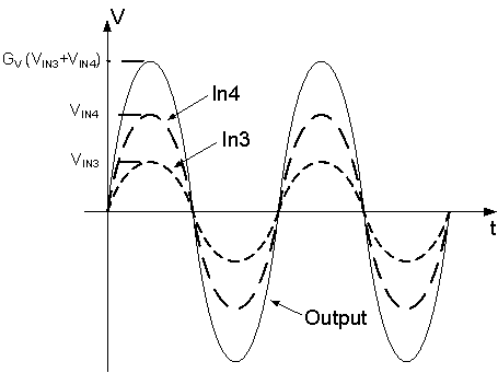 Figure 4: Input and Output Waveforms of the Summing Op-amp
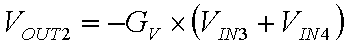
The relationship between the Input Voltages, VIN3 and VIN4, and the Output Voltage VOUT2 of the Summing Op-amp is expressed as follows:
About CMM
Contact US
Others
Other Websites
Number of Visitors:
Last Modified Date: 10/3/2025