Logic gates II
Exclusive NOR (XNOR) and Exclusive OR (XOR) Gates
Half Adder and Basic (1-bit) Full Adder
Logic Gates are basic building blocks in Digital Electronics. The relation between the Input(s) and the Output of a Logic Gate is expressed with a Truth-Table.
Exclusive NOR (XNOR) and Exclusive OR (XOR) Gates
An XOR Gate is a Logic Gate that has two or more than two Inputs, its Output is 1 only when exactly one of its Inputs is 1. The Schematic Symbol of a Two-Input XOR Gate is shown in Figure 1 and Table 1 is its Truth-Table.
The notation of the logic operation of XOR Gate can be expressed by:


Figure 1: XOR Gate Schematic Symbol
| A | B | Q |
|---|---|---|
| 0 | 0 | 0 |
| 0 | 1 | 1 |
| 1 | 0 | 1 |
| 1 | 1 | 0 |
Table 1: XOR Gate Truth-Table
An XNOR Gate is a Logic Gate that has two or more than two Inputs, its Output is 1 only when all its Inputs are set to the same Logic State. The Schematic Symbol of a Two-Input XNOR Gate is shown in Figure 2 and Table 2 is its Truth-Table.
The notation of the logic operation of XNOR Gate can be expressed by:
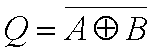

Figure 2: XNOR Gate Schematic Symbol
| A | B | Q |
|---|---|---|
| 0 | 0 | 1 |
| 0 | 1 | 0 |
| 1 | 0 | 0 |
| 1 | 1 | 1 |
Table 2: XNOR Gate Truth-Table
Half Adder and Basic (1-bit) Full Adder
In electronics, an Adder is a device that performs the addition of two numbers.
A Half Adder is a Logic Circuit that performs 1-bit binary addition. Given that P and Q are two 1-bit binary numbers, S is the 1-bit Sum of P and Q, and CO is the CARRY OUT bit. Mathematically, as shown in Figure 3, S and CO form a 2-bit Arithmetic Sum of P and Q, with CO being the Most Significant Bit (MSB). Figure 4 shows all possible cases for 1-bit binary addition and Table 3 is the Half Adder Truth-Table.
| 1 | ←P | ||
| +) | 1 | ←Q | |
| 1 | 0 | ||
| ↑ | ↑ | ||
| CO | S | ||
Figure 3: Addition of two 1-bit binary numbers
| 0 + 0 = 0 |
| 0 + 1 = 1 |
| 1 + 0 = 1 |
| 1 + 1 = 0 with a Carry of 1 |
Figure 4: All possible cases for 1-bit binary addition
| Inputs | Outputs | ||
|---|---|---|---|
| P | Q | CO | S |
| 0 | 0 | 0 | 0 |
| 0 | 1 | 0 | 1 |
| 1 | 0 | 0 | 1 |
| 1 | 1 | 1 | 0 |
Table 3: Half Adder Truth-Table
According to the Truth-Table, if we consider the logic relation between the Inputs and Outputs of a Half Adder, S is the XOR operation of the Inputs and CO is the AND operation of the Inputs. This means that the Half Adder circuit can be implemented with just two Logic Gates: an XOR Gate and an AND Gate, Figure 5.
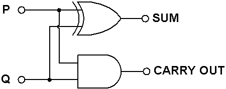
Figure 3: Half Adder
The Half Adder can only perform the addition of two 1-bit binary numbers, because it does not accept the Input of a carry bit from the addition of two previous bits.
A Basic (1-bit) Full Adder is a Logic Circuit that performs the addition of two 1-bit binary numbers with a carry bit, CARRY IN (CI). It consists of one OR Gate and two Half Adders, Figure 6. The circuit generates two Outputs: S and CO. Multiple Basic Full Adders can be cascaded to form a Multi-bit Full Adder.
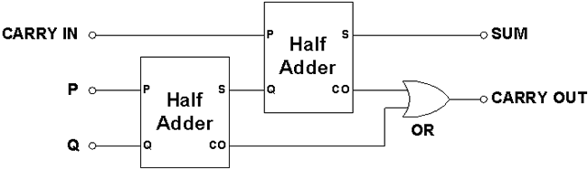
Figure 6: Basic (1-bit) Full Adder
Full Adder (4-bit)
Multiple Basic (1-bit) Full Adders can be cascaded to form a Multi-bit Full Adder. In Figure 7, four Basic Full Adders are chained together to form a 4-bit Ripple Adder, with the Carry Out (CO) of a Basic Full Adder connected to the Carry In (CI) of the next most significant Basic Full Adder.
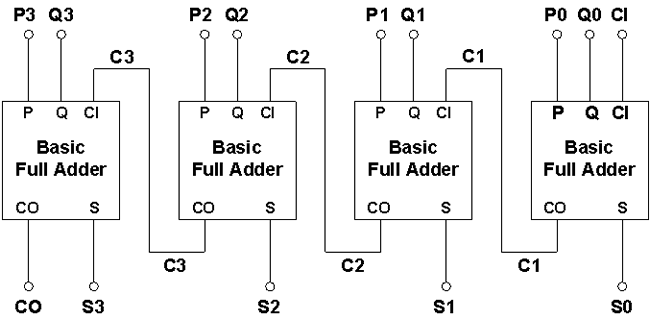
Figure 7: A 4-bit Ripple Adder constructed with four Basic Full Adders
Addition between two Multi-bit Binary Numbers P and Q is done by adding the bits successively, starting from the Least Significant Bit (LSB), i.e. P0 + Q0. Any Carry bit from previous bits is added to the sum of the next consecutive bits, Figure 8.
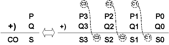
Figure 8: Addition of two 4-bit Binary Numbers illustrating Carry operation
For a 5-bit Binary Number P, the weights of its significant bits are:
| P0 = 20 = 1 |
| P1 = 21 = 2 |
| P2 = 22 = 4 |
| P3 = 23 = 8 |
| P4 = 24 = 16 |
The formula for converting a 5-bit Binary Number P2 (P4 P3 P2 P1 P0) to its corresponding Decimal Number P10 is:
P10 = P4 x 24 + P3 x 23 + P2 x 22 + P1 x 21 + P0 x 20
The CO bit of a 4-bit Full Adder is equivalent to the 4th significant bit and its weight is 16 (24 = 16).
The largest decimal sum that can be obtained from a 4-bit Full Adder is 31 (24+1 - 1 = 31).
About CMM
Contact US
Others
Other Websites
Number of Visitors:
Last Modified Date: 10/3/2025