Transformer
A Transformer is an electrical device that transfers Electric Energy from one Circuit to another by Magnetic Coupling without using any moving parts, Figure 1.
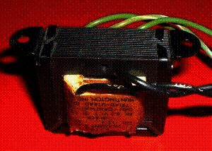 Figure 1: Transformer
As shown in Figures 2a and 2b, Coil A is fed with a varying Electric Current, and a varying Magnetic Field is created. If Coil B is placed close enough to Coil A, the varying Magnetic Field would induce an Electromotive Force (e.m.f.) in Coil B. This property is called Mutual Inductance.
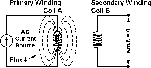 Figure 2a: The Magnetic Flux Generated in the Primary Winding cannot reach the Secondary Winding, no e.m.f. is Induced in it
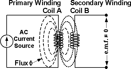 Figure 2b: The Magnetic Flux Generated in the Primary Winding reaches the Secondary Winding, an e.m.f. is Induced in it
A Transformer is commonly made of an Iron Core on which are wound a pair of Windings (Coils) which have different numbers of turns, N1 and N2, Figure 3. The Winding connected to the AC Power Source is called the Primary Winding (Coil A), and the Winding connected to the Load is called the Secondary Winding (Coil B).
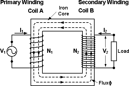 Figure 3: The Basic Structure of a Transformer
The ratio of the Voltages in the two Windings is the same as the ratio of their number of turns.
V1 / V2 = N1 / N2
Power, P, is equal to the product of Voltage, V, and Current, I. The Power on both sides of the ideal Transformer should be the same. The relationship between P, V, I and N is summarized as below:
P = V1 x I1 = V2 x I2
I1 / I2 = V2 / V1 = N2 / N1
However, practical Transformers have Energy losses, which reduce the Output Power.
Three of the basic applications of a Transformer are: to step up or step down the Voltage or Current, to act as an Impedance matching device, and to Isolate (no physical connection) one portion of a circuit from another.
About CMM
Contact US
Others
Other Websites
Number of Visitors:
Last Modified Date: 10/3/2025