BJT Lab
A Bipolar Junction Transistor (BJT) is a three-terminal semiconductor device. It may work as an Amplifier, in which it operates in linear amplification mode, or work as an Electronic Switch, in which it operates alternately in cutoff and saturation mode.
The three basic configurations of BJT Amplifier are: Common-Emitter (CE) Amplifier, Common-Collector (CC) Amplifier and Common-Base (CB) Amplifier.
Figure 1 shows the circuit of a Common-Emitter (CE) Amplifier. The Input Signal is at the Base, the Output Signal is at the Collector and the Emitter is at ground for AC signals due to the Bypass Capacitor C3. C1 and C2 are the Coupling Capacitors for the Input and Output Signals respectively.
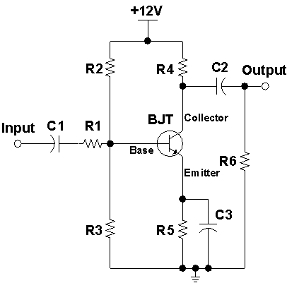 Figure 1: Circuit of a BJT Common-Emitter Amplifier
The CE Amplifier provides a high Current Gain (around -100) and a moderate-to-high Voltage Gain (around -10 to -100). It has moderate-to-high Input and Output Resistances (around 1 kΩ to 1 MΩ). There is a Phase Shift of 180˚ from input to output.
The CE Amplifier is the most versatile of the three basic BJT Amplifier configurations. It is often used to amplify weak voltage signals.
About CMM
Contact US
Others
Other Websites
Number of Visitors:
Last Modified Date: 10/3/2025