ADC and DAC
Digital to Analog Converter
In modern life, electronic equipment is frequently used in different fields such as communication, transportation, entertainment, etc. Analog to Digital Converter (ADC) and Digital to Analog Converter (DAC) are very important components in electronic equipment. Since most real world signals are analog, these two converting interfaces are necessary to allow digital electronic equipments to process the analog signals. Take the audio signal processing in Figure 1 as an example, ADC converts the analog signal collected by audio input equipment, such as a microphone, into a digital signal that can be processed by computer. The computer may add sound effect such as echo and adjust the tempo and pitch of the music. DAC converts the processed digital signal back into the analog signal that is used by audio output equipment such as a speaker.
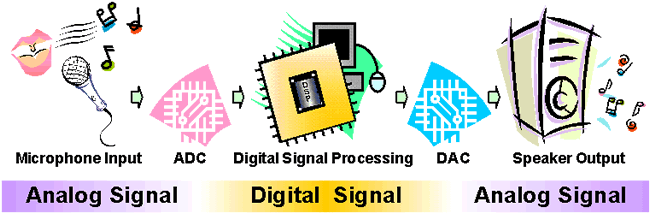
Figure 1: Audio signal processing
A DAC can be constructed by using a Summing Amplifier and a set of resistors R, 2R, 4R and 8R as its inputs, Figure 2. The resistors are scaled to represent weights for the different input bits.
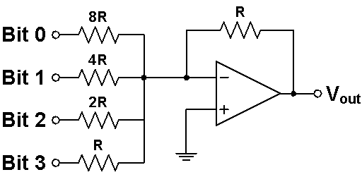
Figure 2: A Summing Amplifier functioning as a simple DAC
The resistor with the lowest value R corresponds to the highest weighted binary input Bit 3 (MSB) [23 = 8], and 2R, 4R, 8R correspond to the binary weights of Bit 2 (22 = 4), Bit 1 (21 = 2), and Bit 0 (LSB) [20 = 1] respectively. The relationship between the digital inputs (Bit 0 to Bit 3) and the analog output VOUT is as follow:
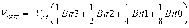
where Vref is the Reference Voltage of the circuit. Assuming the value of Vref as 5 V, the Analog Output Voltages corresponding to the Digital Input Codes is shown in Table 1.
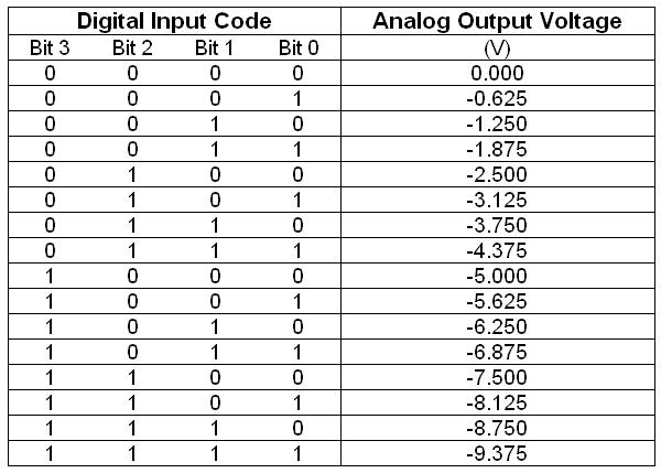
Table 1: The Analog Output Voltages corresponding to the Digital Input Codes with Vref = 5 V
Analog To Digital Converter
In electronics, an Analog to Digital Converter (ADC) is a device for converting an analog signal (current, voltage etc.) to a digital code, usually binary. In the real world, most of the signals sensed and processed by humans are analog signals. Analog-to-Digital conversion is the primary means by which analog signal are converted into digital data that can be processed by computers for various purposes, Figure 3.

Figure 1: Audio Signal Processing
There are many types of ADC for different applications. The most inexpensive type of ADC is a Successive-Approximation ADC. Figure 4 shows the transfer curve of a 4-bit ADC. Inside a Successive-Approximation ADC, a series of digital codes, each corresponds to a fix analog level, are generated successively by an internal counter to compare with the analog signal under conversion. The generation is stopped when the analog level becomes just larger than the analog signal. The digital code corresponds to the analog level is the desired digital representation of the analog signal.
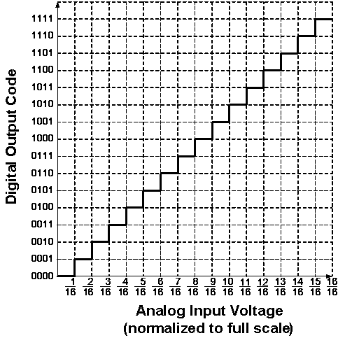
Figure 2: Ideal Transfer Curve of a 4-bit ADC
The performance of ADCs and DACs mainly depends on their Resolution and Speed.
The Resolution of a converter is expressed in the number of Bit. For an ADC, the Resolution states the number of intervals or levels which can be divided from a certain analog input range. An n-bit ADC has the resolution of 1 / 2n. For example, the Resolution of a 16-bit ADC is 1 / 65536, since 216 = 65536. If the measuring voltage range is 10 V, then this input range can be resolved into 10 V / 65536 = 0.153 mV precision.
The Speed of a converter is expressed by the Sampling Frequency. It is the number of times that the converter samples the analog signal, its unit is Hertz (Hz). In audio signal processing, Sampling Frequencies of 44 kHz, 22 kHz and 11 kHz are mostly used. Using 44 kHz Sampling Frequency means the converter is sampling the analog audio signal and doing analog to digital conversion at 44000 times per second. The higher the Sampling Frequency, the lower the distortion and the better the sound quality.
ADCs are used virtually everywhere, whenever an analog signal has to be transported, it is processed and stored in digital form. They are always used together with different transducers to convert physical sense and measurement such as temperature, pressure, humidity, speed, vibration, sound, picture etc. in digital signal for further processing by microprocessor.
1-Digit Voltmeter
A Voltmeter is a measuring instrument for measuring the Voltage between two points in an electric circuit.
This Exhibit is a simple application of the ADC for measuring the value of an analog input. Figure 4 is its block diagram. The 1-Digit Voltmeter consists of an ADC, a Clock Generator, a 4-bit Binary Counter, a BCD to 7-Segment Decoder and a 7-Segment LED Display.
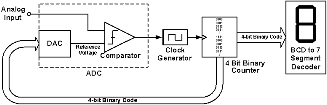
Figure 1: Block diagram of the 1-Digit Voltmeter
The operation flow is as follow:
- Initially, the DAC Reference Voltage is set to zero, which is smaller than the Analog Input, therefore the Comparator outputs a signal to enable the Clock Generator.
- The Binary Counter receives the Clock Signal and increases the Binary Code, from (0000)2 towards (1111)2.
- The DAC converts this 4-bit Binary Code into a new Reference Voltage.
- This Reference Voltage is compared to the Analog Input again. If it is still smaller than the Analog Input, the above cycle continues. If it is larger than the Analog Input, the Comparator will change its output and disable the Clock Generator, the Binary Counter stops increasing, and the conversion of the Analog Input to a Binary Code is done.
- This resulting Binary Code is the one that causes the DAC to produce an analog voltage that is as close as to the analog input as possible without exceeding it.
- This Binary Code is fed to the BCD to 7-Segment Decoder to drive the 7-Segment LED to display the 1-digit decimal value.
About CMM
Contact US
Others
Other Websites
Number of Visitors:
Last Modified Date: 10/3/2025