Logic gates I
Inverter (NOT Gate) and Buffer
Digital Circuit operates at two different Voltage Levels, Low and High. Generally, the Low Level corresponds to Logic 0 and the High Level corresponds to Logic 1. Logic Gates are basic building blocks in Digital Electronics. The relation between the Input(s) and the Output of a Logic Gate is expressed with a Truth-Table.
Inverter (NOT Gate) and Buffer
An Inverter is a Logic Gate that has only one Input, it outputs the opposite Logic State of its Input. The Inverter is also called NOT Gate. The Schematic Symbol of a basic Inverter is shown in Figure 1 and Table 1 is its Truth-Table.
The notation of the logic operation of Inverter can be expressed by:

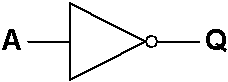
Figure 1: Inverter (NOT Gate) Schematic Symbol
| A | Q |
|---|---|
| 0 | 1 |
| 1 | 0 |
Table 1: Inverter (NOT Gate) Truth-Table
A Buffer is another Logic Gate that has only one Input, its Output follows the same Logic State as the Input. The Buffer is used as delay element in Digital Electronics. It is also a Current-Boost-Up element, which is used to increase the capability of the Output of one gate to drive a number of other gates. The Schematic Symbol of a Buffer is shown in Figure 2 and Table 2 is its Truth-Table.
The notation of the logic operation of Buffer can be expressed by:

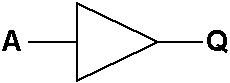
Figure 2: Buffer Schematic Symbol
| A | Q |
|---|---|
| 0 | 0 |
| 1 | 1 |
Table 2: Buffer Truth-Table
NAND and AND Gates
An AND Gate is a Logic Gate that has two or more than two Inputs, its Output is 1 only when all its Inputs are 1. The Schematic Symbol of a Two-Input AND Gate is shown in Figure 3 and Table 3 is its Truth-Table.
The notation of the logic operation of AND Gate can be expressed by:
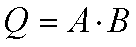

Figure 3: AND Gate Schematic Symbol
| A | B | Q |
|---|---|---|
| 0 | 0 | 0 |
| 0 | 1 | 0 |
| 1 | 0 | 0 |
| 1 | 1 | 1 |
Table 3: AND Gate Truth-Table
A NAND Gate is another Logic Gate that has two or more than two Inputs, its Output is 0 only when all its Inputs are 1. The Schematic Symbol of a Two-Input NAND Gate is shown in Figure 4 and Table 4 is its Truth-Table.
The notation of the logic operation of NAND Gate can be expressed by:
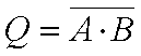
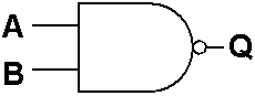
Figure 4: NAND Gate Schematic Symbol
| A | B | Q |
|---|---|---|
| 0 | 0 | 1 |
| 0 | 1 | 1 |
| 1 | 0 | 1 |
| 1 | 1 | 0 |
Table 4: NAND Gate Truth-Table
NOR and OR Gates
An OR Gate is a Logic Gate that has two or more than two Inputs, its Output is 0 only when all its Inputs are 0. The Schematic Symbol of a Two-Input OR Gate is shown in Figure 5 and Table 5 is its Truth-Table.
The notation of the logic operation of OR Gate can be expressed by:
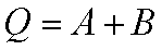
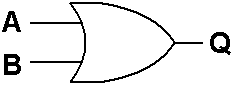
Figure 5: OR Gate Schematic Symbol
| A | B | Q |
|---|---|---|
| 0 | 0 | 0 |
| 0 | 1 | 1 |
| 1 | 0 | 1 |
| 1 | 1 | 1 |
Table 5: OR Gate Truth-Table
A NOR Gate is a Logic Gate that has two or more than two Inputs, its Output is 1 only when all its Inputs are 0. The Schematic Symbol of a Two-Input NOR Gate is shown in Figure 6 and Table 6 is its Truth-Table.
The notation of the logic operation of NOR Gate can be expressed by:
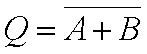
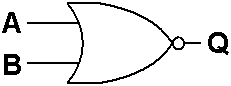
Figure 6: NOR Gate Schematic Symbol
| A | B | Q |
|---|---|---|
| 0 | 0 | 1 |
| 0 | 1 | 0 |
| 1 | 0 | 0 |
| 1 | 1 | 0 |
Table 6: NOR Gate Truth-Table
About CMM
Contact US
Others
Other Websites
Number of Visitors:
Last Modified Date: 10/3/2025