Counters and Multiplexing
High Low Binary Guessing Game
This Exhibit utilizes a Comparator and a 4-bit Counter to implement a Binary Number Guessing Game.
A Random 4-bit Binary Number Q is generated by the Counter. You guess the value of Q by inputting another 4-bit Binary Number P. If the Correct Binary Number is inputted, the Comparator will turn on the LED CORRECT and the game is finished.
If the Inputted Binary Number is not correct, the Comparator will indicate whether your Input Number P is lower (LED TOO LOW will light up) or higher (LED TOO HIGH will light up) than Random Generated Number Q.
Table 1 is the possible outputs of the Binary Counter, that is, the possible values of the number Q. To minimize the number of guesses, Bisection Method can be used. Start from the largest number and use the hint from the Comparator, you can reduce the guessing range by half each time. Therefore, from Table 1, within four trials, the unknown number Q can be figured out.
| Decimal | Binary | |||
|---|---|---|---|---|
| Q3 | Q2 | Q1 | Q0 | |
| 0 | 0 | 0 | 0 | 0 |
| 1 | 0 | 0 | 0 | 1 |
| 2 | 0 | 0 | 1 | 0 |
| 3 | 0 | 0 | 1 | 1 |
| 4 | 0 | 1 | 0 | 0 |
| 5 | 0 | 1 | 0 | 1 |
| 6 | 0 | 1 | 1 | 0 |
| 7 | 0 | 1 | 1 | 1 |
| 8 | 1 | 0 | 0 | 0 |
| 9 | 1 | 0 | 0 | 1 |
| 10 | 1 | 0 | 1 | 0 |
| 11 | 1 | 0 | 1 | 1 |
| 12 | 1 | 1 | 0 | 0 |
| 13 | 1 | 1 | 0 | 1 |
| 14 | 1 | 1 | 1 | 0 |
| 15 | 1 | 1 | 1 | 1 |
Table 1: Counting Sequence of a 4-bit Binary Counter
Demultiplexer
Demultiplexing is the technique to separate a multiplexed signal (Single Channel) into its original multiple Data Streams. In electronics, the Demultiplexing circuit is often integrated in a single chip called Demultiplexer or DEMUX.
Actually, Demultiplexing is a reverse process of Multiplexing does. Therefore the Multiplexing and Demultiplexing must directly cooperate.
In Time-Division Demultiplexing, the received composite signal is decomposed into pieces of Time Slots according to the Multiplexing, Figure 1. The data on the Time Slots are reorganized to setup the original multiple Data Streams and routed to the proper end-users.
It is usual to combine a Multiplexer and a Demultiplexer together into one piece of equipment and simply refer to the whole module as a "Multiplexer". Both Multiplexer and Demultiplexer are needed at both ends of a transmission link because most communications systems transmit in both directions.
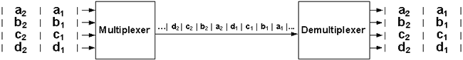
Figure 1: Block Diagram of the Multiplexer / Demultiplexer
Multiplexer
Multiplexing is the technique to transmit multiple Data Streams over a Single Channel. In electronics, the Multiplexing circuit is often integrated in a single chip called Multiplexer or MUX.
In electrical communications, the two basic forms of Multiplexing are Time Division Multiplexing (TDM) and Frequency Division Multiplexing (FDM). In optical communications, the counterpart of FDM is referred to as Wavelength Division Multiplexing (WDM).
Time-Division Multiplexing (TDM), Figure 1, divides transmission time on a Single Channel into non-overlapped Time Slots. Bit(s) of data from successive Data Streams are interleaved into the Time Slots, each having a very short duration. The data on the Time Slots are combined into a composite signal in a rotating, repeating sequence. The composite signal thus contains data from multiple senders, and can be transmitted over a Single Channel.
At the other end of the long-distance cable, the individual Data Streams are separated out by means of a circuit called Demultiplexer, and routed to the proper end-users.
A Bi-directional communication circuit requires a Multiplexer / Demultiplexer module at each end of the long-distance, high-bandwidth cable.
Figure 2 : Block Diagram of the Multiplexer / Demultiplexer
About CMM
Contact US
Others
Other Websites
Number of Visitors:
Last Modified Date: 10/3/2025