JFET Lab
Analog Lab > JFET Lab
The Field Effect Transistor (FET) is another major type of transistor besides the Bipolar Junction Transistor (BJT). FETs rely on an Electric Field to control the conductivity of a Channel in a semiconductor material. There are two general classes of FETs: the Metal-oxide-semiconductor FET (MOSFET) and the Junction FET (JFET).
The Junction Field Effect Transistor (JFET) can be configured as an Amplifier in which it operates in linear amplification mode. Like the BJT, it can also be configured as an Electronic Switch, in which it operates alternately in cutoff and triode mode.
There are three basic configurations of JFET Amplifier: the Common-Source (CS) Amplifier, the Common-Drain (CD) Amplifier and the Common-Gate (CD) Amplifier.
For a Common-Source (CS) Amplifier, which is shown in Figure 1, the Input Signal is at the Gate, the Output Signal is at the Drain and the Source is at ground for AC signals due to the Bypass Capacitor C3. C1 and C2 are the Coupling Capacitors for the Input and Output Signals respectively. The CS Amplifier is analogous to the BJT Common-Emitter Amplifier.
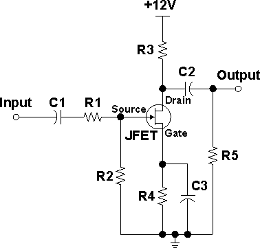
Figure 1: Circuit of a JFET Common-Source Amplifier
The CS Amplifier provides almost an infinite Current Gain and a moderate Voltage Gain (around -10). It has an extremely high Input Resistance (around 100 MΩ) and a high Output Resistance (around 500 kΩ). There is a Phase Shift of 180° from Input to Output.
The CS Amplifier is the most versatile of the three basic JFET amplifier configurations. It is often used to amplify voltage signals, and used as the Input of the next stage.
Analog Lab > JFET Lab
About CMM
Contact US
- Number of Visitors:
- Last Modified Date: 4/7/2023