Displays
Digital Lab > Displays
7-Segment Light Emitting Diode (LED) Display
7-Segment Liquid Crystal Display (LCD)
7-Segment Light Emitting Diode (LED) Display
Numbers can be represented in different numerical systems with different bases. In daily life, we represent a number using the digits 0 to 9. This is the decimal system and the base is 10. In digital electronics, only two states, Low and High, are used to represent the digits 0 and 1. This is the binary system and the base is 2. Each digit in a binary number is called a bit, which comes from the English words "binary digit".
Four Inputs A to D are used to control the number displayed on the LED Display. The Inputs are arranged in the sequence "DCBA" to represent a 4-bit Binary Number. Their weights are as follows:
| Input D is the Most Significant Bit: (MSB) 23 = 8 |
| Input C is the Second Significant Bit:(2ndSB) 22 = 4 |
| Input B is the Third Significant Bit: (2rdSB) 21 = 2 |
| Input A is the Least Significant Bit: (LSB) 20 = 1 |
The conversion between a 4-bit Binary Number and a Decimal Number is:
Decimal Number = D x 23 + C x 22 + B x 21 + A x 20
7-Segment LED Display is a form of displaying decimal Arabic number in electronics. It predates the widely used Dot-Matrix Displays nowadays. A 7-Segment LED Display is composed of seven segments, Figure 1. Each segment is a LED. They are combined to produce standardized representations of the decimal Arabic numbers.
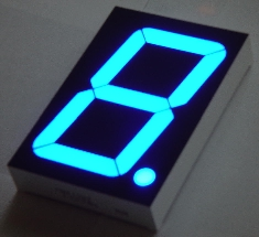
Figure 1: A 7-Segment LED Display
An Integrated Circuit (IC) chip, BCD to 7-Segment Decoder, is used to convert the four binary Inputs A to D to seven Outputs, which drive the 7-Segment LED Display. BCD means Binary Coded Decimal. Table 1 shows the relation between the binary Inputs, Decoder Outputs and decimal numbers 0 to 9. Figure 2 is the diagram of a display module with a BCD to 7-Segment Decoder and a 7 Segment-LED Display.
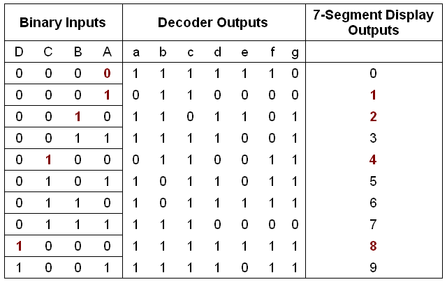
Table 1: BCD to 7-Segment Decoder Truth-Table
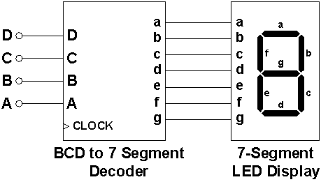
Figure 2: The diagram of a display module with a BCD to 7-Segment Decoder and a 7 Segment-LED Display
7-Segment Liquid Crystal Display (LCD)
A Liquid Crystal Display (LCD) is a thin, flat device made up of various colors or monochrome pixels arrayed in front of a Light source or reflector.
Light travels as Electromagnetic Waves vibrating in a plane perpendicular to the Light Ray direction. For normal Light, the vibration direction within this plane is random. In a LCD, a polarizer allows Light vibrating only in a certain direction to pass through, and the Light is then said to be polarized, Figure 3.
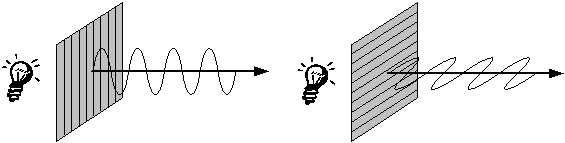
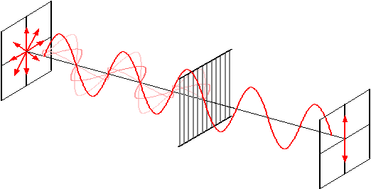
Figure 1: Light can be polarized by a polarizer
The operating principle of a LCD is shown in Figures 4a and 4b. If there is no voltage applied to the LCD, Light entering from the top side of the LCD is polarized by the first polarizer. The layers of liquid crystal molecules between the two polarizers guide the Light passing through them with a gradual twist angle, and change the direction of vibration of the Light. When the Light passes through the last layer of liquid crystal molecules, it is twisted 90° degree relative to the first polarizer and vibrates at the same angle as the second polarizer. Light passes through the second polarizer and is reflected by a mirror on the bottom side. The area covered by the segment appears bright.
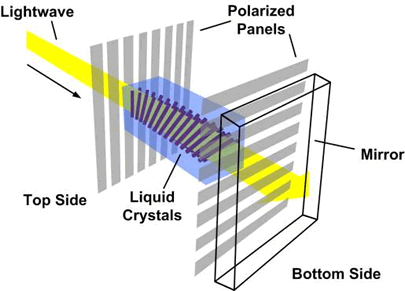
Figure 4a: Light wave is polarized and twisted when no voltage is applied
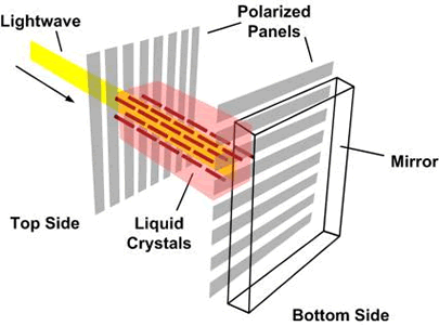
Figure 4b: Light wave is blocked when voltage is applied
If a voltage is applied between the first and the second polarizers, an Electric Field is setup between them. The liquid crystal molecules between the polarizers align up in order with the Electric Field direction. The polarized Light passes through all layers of liquid crystal molecules directly without twisting, and is vibrating perpendicularly to the second polarizer. Consequently, no Light can pass through the second polarizer and no Light is reflected by the mirror, the area covered by the segment appears dark.
The LCD Display must not work directly under DC Voltage since the Electric Field direction becomes fixed. This will cause the molecules of liquid crystal to split up into positive and negative particles.Therefore a square wave clock signal is required to reverse the direction of the Electric Field.
Dot-matrix Display
A Dot-matrix Display is a device consisting of small light-emitting elements, which are arranged as a two-dimensional array. By energizing different elements, a Dot-matrix Display can depict different characters that have greater resolution than a segmented Display.
A Dot-matrix Display accepts an input of a 7-bit Binary Number. The most widely used encoding standard is called ASCII (American Standard Code for Information Interchange), which is a character encoding standard used to represent character information in Digital Electronics. It is a 7-bit code, which uses A0 to A6 to represent the decimal numbers from 0 to 127, with A0 being the LSB and A6 being the MSB.
The first thirty-two codes (0 to 31) in ASCII are reserved for control codes that control computer equipment (such as printers). For example, code 10 represents the "line feed" function (which causes a printer to advance its paper). Table 1 shows the printable characters with the ASCII.
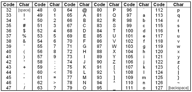
Table 2: The printable characters of ASCII and the corresponding decimal codes
Digital Lab > Displays
About CMM
Contact US
- Number of Visitors:
- Last Modified Date: 4/7/2023