Phase Shift
AC-Circuits > Phase Shift
Generally, AC circuits may contain Resistors, Inductors and (or) Capacitors. Impedance, represented by the letter "Z" and measured in Ohms, is the total opposition that a circuit offers to the flow of AC Current, it is a combination of Resistance R and Reactance X, Z = R + jX, Figure 1.
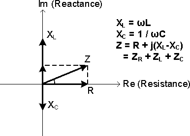
Figure 1: Impedance Diagram
In AC circuits, because the existence of Reactive Components, the Voltage and Current may not reach the same amplitude peaks at the same time, they generally have a difference in timing. This timing difference is called Phase Shift, f, 0° ≤ f ≤ 90°, and is measured in angular degrees.
A circuit that contains only Resistors is called Resistive Circuit. There is no Phase Shift between the Voltage and the Current in a Resistive Circuit, Φ = 0°, Figure 2a. The Current is "In-Phase" with the Voltage.
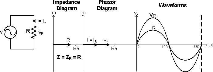
Figure 2a: V-I Relationship of the Circuit R
Capacitors and Inductors are called Reactive Components, in which the Voltage and Current are "Out-of-Phase" with each other. In an Inductor, the Voltage leads the Current by 90°, Φ = 90°, Figure 2b; in a Capacitor, the Voltage lags the Current by 90°, Φ = -90°, Figure 2c.
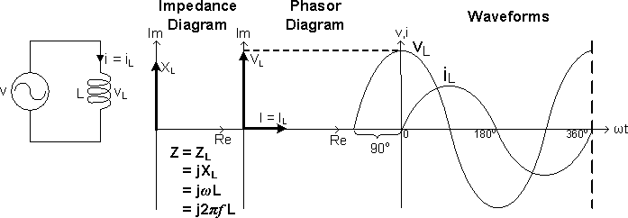
Figure 2b: V-I Relationship of Circuit L
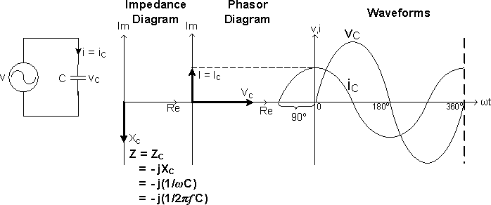
Figure 2c: V-I Relationship of Circuit C
A circuit that contains Inductors and (or) Capacitors is called Reactive Circuit, which can be classified into Inductive Circuit, XL > XC, and Capacitive Circuit, XC > XL.
Figure 3a shows an Inductive Circuit that consists of R and L in series. As the Inductor opposes a change in Current and stores energy from the Power Supply in the form of a Magnetic Field, the Inductor Voltage vL leads the Inductor Current iL by 90° and leads the Power Supply Voltage v by a Phase Angle Φ.
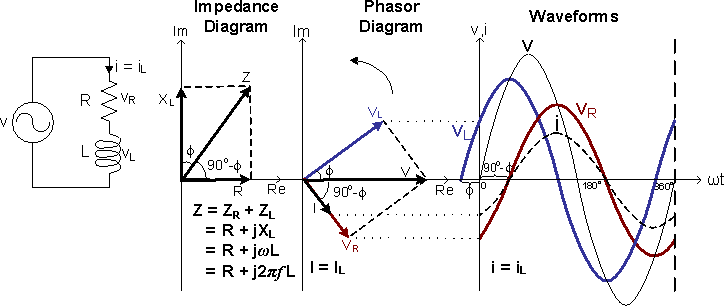
Figure 3a: V-I Relationship of the Circuit RL
Figure 3b shows a Capacitive Circuit that consists of R and C in series. As the Capacitor opposes a change in Voltage and stores energy from the Power Supply in the form of an Electric Field, the Capacitor Voltage vC lags the Capacitor Current iC by 90° and lags the Power Supply Voltage v by a Phase Angle Φ.
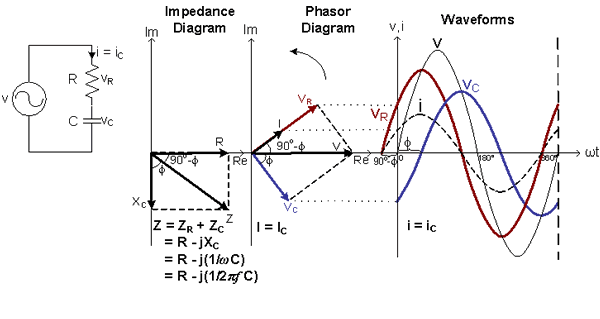
Figure 3b: V-I Relationship of the Circuits RC
AC-Circuits > Phase Shift
About CMM
Contact US
- Number of Visitors:
- Last Modified Date: 4/7/2023