Resonant Circuit
AC-Circuits > Resonant Circuit
Figure 1 shows a Series RLC Circuit, Figure 1, where R is a Resistor, L is an Inductor and C is a Capacitor. The total Impedance Z of this circuit for any Frequency of the Power Supply Voltage is determined by:

where R is the Resistance, XL = 2πfL and XC = 1 / (2πfC) are the Reactance of the Inductor and Capacitor respectively, measured in Ohms.
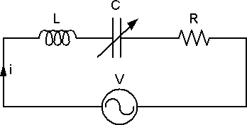
Figure 1: Series RLC Circuit
For a certain Capacitance of the Variable Capacitor C, XL is equal to XC. The two Phase Shifts caused by the Capacitor and the Inductor are opposite to each other, so the total Reactance of the circuit becomes zero.
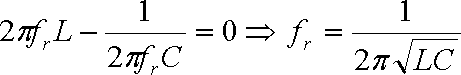
The circuit can be treated as a pure Resistive Circuit, Figure 2. At this moment, the circuit is at Resonance and the Frequency at which this occurs is called the Resonance Frequency fr.
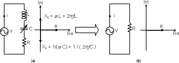
Figure 2: When the total Reactance of a Series RLC Circuit becomes Zero, the circuit is equivalent to a pure Resistive Circuit
The Capacitor and the Inductor are Reactive Components. Unlike the Resistor, they can store Energy in the form of Electric Field and Magnetic Field respectively and return Energy to the circuit whenever required. At Resonance state, Figure 3, the Energy absorbed by the Inductor is the same as the Energy released by the Capacitor at the interval t1 to t2. The opposite situation occurs at the interval t2 to t3. Therefore all the Energy from the Power Supply is delivered to the Resistor, and the Current in the circuit is maximum.
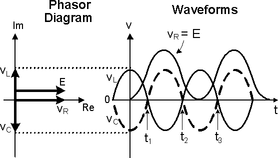
Figure 3: At Resonant state, all the Energy from the Power Supply is delivered to the Resistor
AC-Circuits > Resonant Circuit
About CMM
Contact US
- Number of Visitors:
- Last Modified Date: 4/7/2023